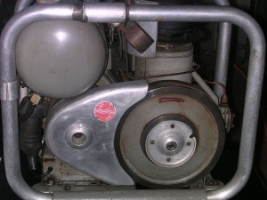
Stirling Engine Basics
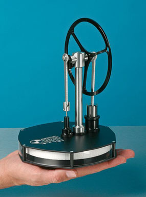
How to make DIY Stirling engines plans, heat engine cycle basics and many homemade examples.
This information is here to help you make better decisions when choosing your DIY Stirling engine project. Also, to help you understand the different types of Stirling engines and how they work.
Image By Arsdell (Own work) [GFDL or CC-BY-SA-3.0-2.5-2.0-1.0], via Wikimedia Commons
What is a Stirling Engine?
The Stirling engine is a closed cycle heat engine. It is typically completely sealed from the outside environment and works on the expansion and compression of the gas (typically air) that's enclosed in the sealed engine. Fuel does not move through the engine like in a conventional internal combustion engine. This means that there is no intake or exhaust.
One side of the engine is heated and the other side is cooled. This causes the gas to go through cycles of expansion and compression. This means it can produce motion by converting heat energy directly into kinetic energy or mechanical work.
An outside of view of the engine shows only it’s moving parts, a heat source and a cooling source. Remember no fuel goes through the motor because it is completely sealed from the outside.
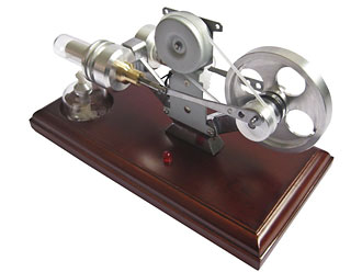
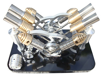
There are many types of Stirling engines. There are high pressure engines that are used commercially. There are restored low pressure engines that are used for display. There are table top model engines built by hobbyists and students.
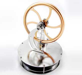
You can find models or kits for almost all of the configurations of Stirling engines including LTD (Low Temperature Differential) engines. An LTD can run on the heat of the palm of your hand.
Fuels That Are Used
The Stirling is traditionally classified as an external combustion engine. Although, properly applied, any heat source will work to power a Stirling engine. This means that the heat source is not limited to combustion only.
Here is a list of some of the possible usable heat sources:
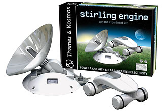
- Solar energy
- Geothermal energy
- Nuclear energy
- Coal
- Gasoline
- Alcohol
- Natural gas
- Propane
- Wood
- Anything that will burn
The Different Types of Heat engines
English Wikipedia user Andrew.Ainsworth [GFDL or CC-BY-SA-3.0], via Wikimedia Commons
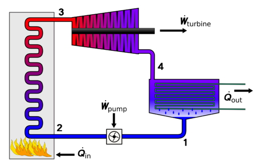
Heat engines are typically accepted as Stirling engines. They’re named after Robert Stirling who was the inventor that created the first practical and usable heat engine in 1816. However, there are many types of heat engines or external combustion engines designed by many other inventors. Some of these use steam as a gaseous working fluid. Others use high pressure water confined in a way to keep it from transitioning to steam.
Names to look for
- Robinson hot air engine
- Heinrici’s hot air engine
- The Ericsson engine
- Malone engine
- Rankine cycle engine
Understanding basic Operation
YK Times at en.wikipedia [GFDL, CC-BY-SA-3.0 or CC-BY-2.5], from Wikimedia Commons
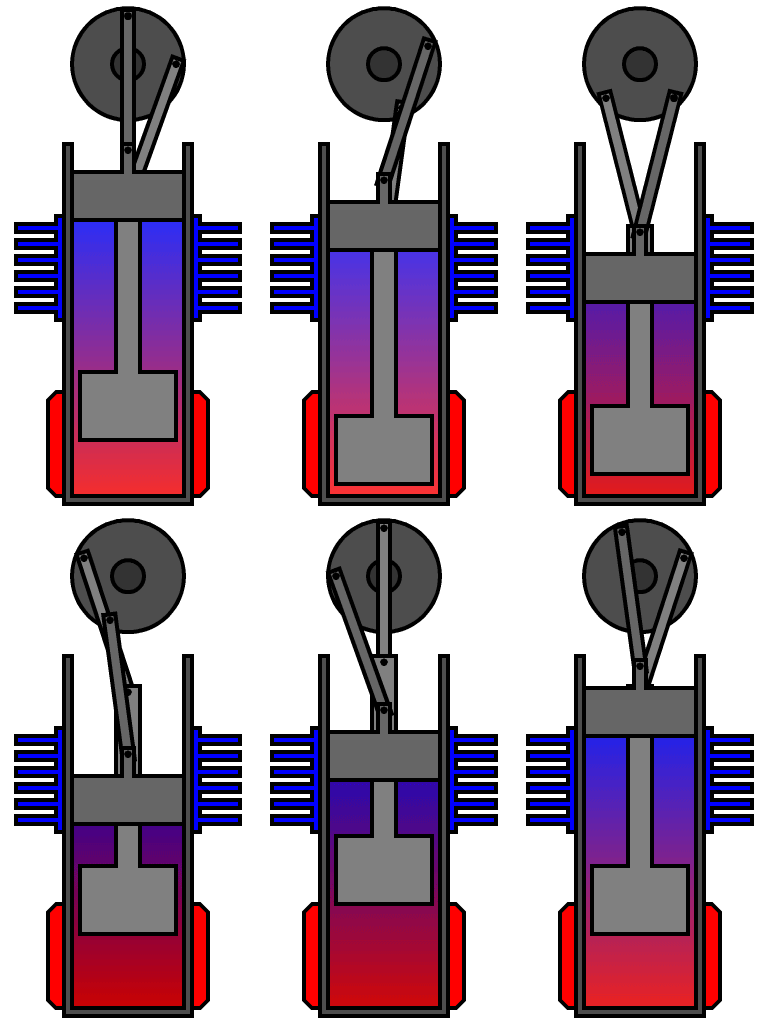
Many Stirling engines have a gas pressure inside them that is nearly equal to the outside atmospheric pressure. There is a fixed mass of gas, typically air, helium or hydrogen. When you heat the outside of the engine the gas expands and pushes the piston out. When you cool it, the gas compresses and the piston is pushed back in by the outside atmospheric pressure. This converts heat energy into mechanical energy or work.
But heating the entire engine then cooling it is not efficient. Because it would require the heating and cooling source to move in and out of position over and over again. So there needs to be a way to heat and cool the engine at the same time. This is done by moving or cycling the gas inside the engine from the hot side to the cool side.
A displacer mechanically moves the gas between a heated location and a cooled location. The displacer is a light weight piston that does not come into contact with the inside of the Stirling engine. The gas can move along the side of the displacer. It moves back and forth taking up space inside the engine displacing the gas from side to side.
When the displacer is on the cool side the gas is pushed to the hot side and it is expanded. When the displacer is on the hot side the gas is pushed to the cool side and it is compressed. This is a simplified explanation of the Stirling cycle which is a type of thermodynamic cycle. This cyclical action needs to be timed correctly. It can be mechanically timed in many different ways. This is why there are so many types and configurations of heat engines.
Types of Stirling Engines
- Alpha Stirling engine
- Beta Stirling engine
- Gamma Stirling engine
- Free piston Stirling engine
- Rotary piston Stirling engine
- Low Temperature difference engine
A great video explaining some principles of a Gamma Stirling engine
The parts of a heat engine
Here is a short description of the parts of a Stirling engine. To help you better understand what goes into a DIY Stirling engine.
The Hot side heat exchanger
This is the hot side of the engine that the outside heat source comes into contact with. It is usually the outside wall of the expansion and compression chamber. It’s also the contact point for the cooled gas. Sometimes to collect as much heat as possible the surface area is increased using internal and or external fins. This works like a heat sink.
The Cold side heat exchanger
This is the part of the engine that the heated gas comes into contact with. It exchanges the heat in the gas to the outside air or cooling fluid. It may also have fins to add to the efficiency. Depending on the engine configuration the cold side heat exchanger can be on the opposite end of the same cylinder as the hot side heat exchanger or on another part of the engine.
The regenerator
The location of the regenerator depends on the engine configuration. Typically the regenerator is an internal heat exchanger that temporarily stores heat that would otherwise be lost between the hot and cold heat exchangers. Sometimes the displacer is made of materials that will allow it to also act as a regenerator. Regenerators are implemented in an attempt to increase efficiency.
The Displacer
This is the part of the engine that moves or displaces the gas (working fluid) from the hot heat exchanger to the cold heat exchanger.
Heat sink
Typically used on the cool side this can be as simple as the outside wall of the engine contacting the ambient air temperature. Although adding fins is more efficient. Also, a radiator can be added to involve water or a coolant.
Flywheel
Relative to the engine the flywheel is a large heavy wheel. It is mechanically connected to the piston(s) of the engine. Its job is to add to the momentum of the machine and help carry the Stirling cycle all the way through. Most heat engines use a flywheel.
The Piston
The piston is typically the same as any other piston that slides inside a cylinder. Although, there some Stirling engine designs that use a flexible membrane to act as a power piston. The piston is pushed out when the working fluid (gas) is expanded enough to exceed the outside atmospheric pressure. This action is often helped along with the use of a flywheel.
Video of a homemade DIY Stirling Engine
Configurations
Alpha Stirling
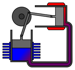
The alpha Stirling has two power pistons, separate hot and cold heat exchangers, a regenerator, and a flywheel. The hot side heat exchanger contains a piston and the cold side heat exchanger contains a piston. Typically no displacer is used. There is usually a high temperature difference between the two pistons. This means higher efficiency and more energy being converted into work. The Alpha Stirling usually offers higher power to weight ratio and faster rotations per minute.
Beta Stirling
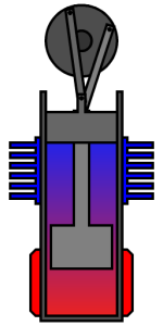
The beta Stirling has one power piston and a displacer that share the same cylinder. The hot and cold heat exchangers also share the same cylinder. Heated at one end and cooled at the other end. The power piston and the displacer are often connected by the flywheel.
Gamma Stirling
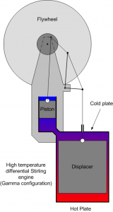
The Gamma Stirling is a variation of the Beta Stirling. It has two cylinders, one for the power piston and one for the displacer. The power piston’s cylinder is located along side of the cylinder that houses the displacer piston. The gas moves through a small port between the two cylinders. The power piston and the displacer are often connected by the flywheel. Some use a regenerator and some don’t.
Ringbom engine
The Ringbom Stirling engine is a variation of the Beta Stirling. It also has two cylinders and one power piston. The power piston is located in its own cylinder that is located along side of the cylinder that houses the displacer piston. The power piston is the only piston connected to the flywheel. The displacer is not connected to the power piston or flywheel. Instead it’s free to move. The displacer piston is smoothly lifted during expansion and dropped during compression.
Free piston Stirling
The free piston Stirling engine is relatively new development. It typically follows the Beta type Stirling piston arrangement. But there is no flywheel or mechanical linkage of that type. They are more likely to be use to generate electricity or be used for refrigeration. This is because they only reciprocate. This means they are ideal for linear alternators. They are usually high pressure engines.
Pressurization
Increasing the working pressure helps increase power and efficiency. This means that the engine starts with a higher mass of gas. More molecules of gas mean more transfer of heat and more work can be done.The Philips MP1002 CA has a working pressure higher than atmospheric pressure. The unit in this video has a starting pressure at about 200 p.s.i. and a running pressure of about 160 p.s.i..But this also means that the engine has to be made of stronger material and have thicker walls. Thicker walls make it more difficult to transfer heat into the gas inside the engine. Most commercially available Stirling engines use gas under pressure.
A heat engine that makes you cold
The thermodynamic cycle of a Stirling can be driven in reverse with the aid of an outside power source. This will cause one side to be heated and the other side to be cooled. Simply put, A Stirling engine can be a heat pump. By spinning the engine through its mechanical cycles the gas inside it is compressed and expanded, heated and cooled, respectively. Cooling with the Stirling cycle is currently used commercially for cryogenics and refrigeration.

